You are here
Cisco ASR 9001 NV Edge System Configuration Guide
Submitted by admin on Thu, 11/07/2013 - 23:11
 Device redundancy is usually the key to increase your network uptime. However, the trade-off of having multiple, almost identical, devices in the network does not only add configuration and management burden to administrators, but also, in most cases, calls for a more complicated design. Cisco virtualization technologies such as stackable switches, Virtual Switching System (VSS), and Virtual Port-channel (vPC), although vCP does not really count since you still have two separate management points, have been created to solve this problem in the switching arena. Such technologies did not exist for routers until now with an introduction of NV Edge System in Cisco ASR 9000 series.

Device redundancy is usually the key to increase your network uptime. However, the trade-off of having multiple, almost identical, devices in the network does not only add configuration and management burden to administrators, but also, in most cases, calls for a more complicated design. Cisco virtualization technologies such as stackable switches, Virtual Switching System (VSS), and Virtual Port-channel (vPC), although vCP does not really count since you still have two separate management points, have been created to solve this problem in the switching arena. Such technologies did not exist for routers until now with an introduction of NV Edge System in Cisco ASR 9000 series.
If you are familiar with VSS and vPC, the concept of NV Edge System might not be foreign to you. NV Edge System allows two ASR 9000 to create a router cluster that appears as a single logical router to external devices as well as provides a unified management point. You can make configuration changes on either routers and the changes will be automatically replicated to the peer router to make sure their configuration remain synchronized. What this means is you no longer need to manually maintain separate copy of configuration or worry about running routing protocol across router interconnect links in any dual-router design. Isn’t that nice?
In this article, we will go through steps to configure a NV Edge System specifically on Cisco ASR 9001. For a more extensive explanation of the technologies and configuration detail for chassis-based ASR 9000, please refer to this Cisco document.
Prerequisites
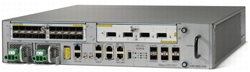
- 2 x Cisco ASR 9001
- 4 x 10G SFP+ (for IRL) and two appropriate fiber cables (minimum)
- 4 x 1G SFP (for Cluster/Control Links) and two appropriate fiber/copper cables
- ASR 9000 NV Cluster License A9K-NV-CLUSTR-LIC(=) (honor-based)
- IOS XR 4.2.x or later (here we use 5.1.0)
From this point on, we will refer to the first or primary ASR 9001 as RACK0 and the second ASR 9001 as RACK1. Note that unlike other ASR 9000 routers, ASR 9001 only has one RSP so between the two routers in a cluster, one RSP will be active while the other will be standby.
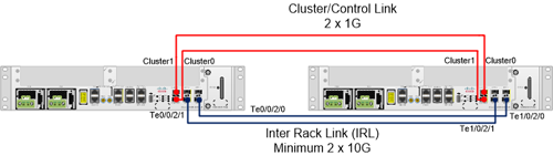
Physical Topology
Cluster/Control Link
- Used for control traffic such as configuration synchronization and keepalive.
- This requires two 1G links.
Inter Rack Link (IRL)
- Used to pass data traffic as it enters one router and exit the other.
- This requires minimum of two 10G links.
- You can use the built-in 10G ports or ports on a 10G MPA, or both for redundancy.
Steps
0. Make sure all IRL are connected and Cluster/Control links are DISCONNECTED
1. Install FPD (minimum 4.2.1)
|
! To Install FPD
install add disk0:/asr9k-fpd-px.pie-5.1.0 active synch
install commit
!
RP/0/RSP0/CPU0:ios(admin)# show hw-module fpd location all
Thu Sep 29 05:44:26.910 PDT
===================================== ==========================================
Existing Field Programmable Devices
==========================================
HW Current SW Upg/
Location Card Type Version Type Subtype Inst Version Dng?
============ ======================== ======= ==== ======= ==== =========== ====
0/RSP0/CPU0 ASR9001-RP 1.0 lc fpga2 0 1.14 No
lc cbc 0 22.114 No
lc rommon 0 2.01 No
--------------------------------------------------------------------------------
0/FT0/SP ASR-9001-FAN 1.0 ft cbc 7 24.114 No
--------------------------------------------------------------------------------
0/0/CPU0 ASR9001-LC 1.0 lc cbc 0 23.114 No
lc fpga2 0 1.18 No
lc fpga4 0 2.07 No
lc rommon 0 2.01 No
--------------------------------------------------------------------------------
0/0/0 A9K-MPA-20X1GE 1.0 spa fpga3 0 0.08 No
--------------------------------------------------------------------------------
0/0/1 A9K-MPA-4X10GE 1.0 spa fpga6 1 1.06 No
|
2. Obtain chassis Serial Number
|
! RACK0
RP/0/RSP0/CPU0:ios(admin)# show inventory chassis
Thu Sep 29 05:46:15.693 PDT
NAME: "chassis ASR-9001", DESCR: "ASR-9001 Chassis"
PID: ASR-9001, VID: V02 , SN: FOC1789GB54
!
! RACK1
RP/0/RSP0/CPU0:ios(admin)# show inventory chassis
Thu Sep 29 05:48:45.233 PDT
NAME: "chassis ASR-9001", DESCR: "ASR-9001 Chassis"
PID: ASR-9001, VID: V02 , SN: FOC178D3DB9
!
|
3. On Rack0, assign S/N to rack position
|
!
nv edge control serial FOC1789GB54 rack 0
nv edge control serial FOC178D3DB9 rack 1
!
|
4. Connect Cluster/Control links
5. Reload RACK1
|
!-------- Reload Here -----------
Starting Initialization of FMAN0
***PPC PROCESSOR REV=2 load FMAN ucode***
Loading ucode for FMAN0, size: 6992, ver: 101.08.00
Starting Initialization of FMAN1
***PPC PROCESSOR REV=2 load FMAN ucode***
Loading ucode for FMAN1, size: 6992, ver: 101.08.00
Serdes Protocol: 0x10
CPU Reset Reason = 0x0001
Initializing GIGE SW...
PPC P40X0 (partnum 0x8023), Revision 02.00, (Core Version 02.00)
Sys Clock: 100 Mhz
Core Clock: 1500 Mhz
Plat Clock: 800 Mhz
LBC Clock: 25 Mhz
MEM Clock: 1300 Mhz
System Bootstrap, Version 2.01(20130627:172232) [ASR9K ROMMON],
Copyright (c) 1994-2013 by Cisco Systems, Inc.
Compiled Fri 28-Jun-13 11:29 by dasomasu
Board Type: 0x100401
CPU Board => Rev: 0x3
=========
FPGA ver: 01.0e
CBC: 16.72
DTI programmed with latest image
TIMEX programmed with latest image
MLAN init done: ready to connect to the network
BCM5482PhyInit (): Port 0 --> SFP Type is SFP_TYPE_FIBER_SFP
BCM5482PhyInit (): Port 1 --> SFP Type is SFP_TYPE_FIBER_SFP
set_chassis_type: chassis_type=0xef0400 found=TRUE
ASR9001E (P40X0 PPC) RSP platform with 8192 Mb of main memory
program load complete, entry point: 0x100000, size: 0x2ac20
Set baud rate to: 9600
program load complete, entry point: 0x100000,
size: 0x2ac20
Set baud rate to: 9600
MBI Candidate = disk0:asr9k-os-mbi-
5.1.0/0x100000/mbiasr9k-rp.vm
CARD_SLOT_NUMBER: 0
CPU_INSTANCE: 1
MBI Validation starts ...
Disabling both Mgt LAN ports
Enabling Cluster Port 0 and disabling Port 1 <---
BCM5482 cluster port-1 reset done !!
BCM5482 cluster port-0 init done !!
dtsec_init_hw: configuring DTSEC (port 8) for: 1GB, Full Duplex
Interface link changed state to UP.
Interface link state up.
MBI validation sending request.
HIT CTRL-C to abort
mbi_val_process_packet: received repsonse (rack 1) [cluster] <---
mbi_val_setup_cluster: my_chassis_type - 0xef0400, peer_chassis_type -
0xef0400
chksum start addr 803c size ec8 checksum is: 0x7c80
chksumnv: Checksum 1 is ffff8380
chksum start addr 803c size ec8 checksum is: 0x0
chksumnv: Checksum 2 is 0
chksum start addr dc200014 size ec8 checksum is: 0x7c80
chksumnv: Checksum 1 is ffff8380
chksum start addr dc200014 size ec8 checksum is: 0x0
chksumnv: Checksum 2 is 0
nvwrite: SUCCESS src=0x0000803c dest=0xdc200014 size=0x00000ec8
NVR=0x00008028 SAV=0xdc200000
chksum start addr 803c size ec8 checksum is: 0x0
NVRAM magic number at location 0x803c is 0xefeedfac chksum loc 8f02
NVRAM confreg 8038 rconfreg 803a
NVRAM Valid: confreg= OK nvmagic= OK chksum= OK
Local image to boot : disk0:asr9k-os-mbi-5.1.0/0x100000/mbiasr9k-rp.vm
Boot Status 16
program load complete, entry point: 0x100000, size: 0x2ac20
Set baud rate to: 9600
MBI size from header = 19094656,Bootflash resident MBI filesize =
19094656
.........................................................................
program load complete, entry point: 0x20261c, size: 0x1234d80
Boot Status 17
Config = SMP, Running = SMP
Board type: 0x00100401
Card Capability = 0x00000000
######################################################################
############################
BSP: Board type : ASR9K-RSP-I
tracelogger: starting tracing in background ring mode
tracelogger running with args: -startring -F 1 -F 2
Restricted Rights Legend
Use, duplication, or disclosure by the Government is
subject to restrictions as set forth in subparagraph
(c) of the Commercial Computer Software - Restricted
Rights clause at FAR sec. 52.227-19 and subparagraph
(c) (1) (ii) of the Rights in Technical Data and Computer
Software clause at DFARS sec. 252.227-7013.
cisco Systems, Inc.
170 West Tasman Drive
San Jose, California 95134-1706
Cisco IOS XR Software for the Cisco XR ASR9K, Version 5.1.0
Copyright (c) 2013 by Cisco Systems, Inc.
Sep 29 12:26:31.632: Install Setup: Using install device 'disk0:'
Sep 29 12:26:45.660: Install Setup: Using MBI device 'bootflash:'
Sep 29 12:26:45.698: Install Setup: Preparing devices:
Sep 29 12:26:45.708: Install Setup: Complete
Sep 29 12:27:09.748: Install Setup: Starting package and meta-data
sync
Sep 29 12:27:09.770: Install Setup: Cleaning packages not in sync list
Sep 29 12:27:09.778: Install Setup: Complete
Sep 29 12:27:28.708: Install Setup: Syncing meta-data:
Sep 29 12:27:30.691: Install Setup: Complete
Sep 29 12:27:30.691: Install Setup: Completed sync of all packages and meta-data
Sep 29 12:27:30.691: Install Setup: Starting MBI sync
Sep 29 12:27:50.725: Install Setup: Completed sync of MBIs
Initializing Punt-switch ...
Initializing Punt-switch ...
Set RP CPU Cluster port in DSA mode <---
Init STP group for Cluster ports forwarding state control done
Cluster: Boot Request Filter configured
Cluster: Control Link monitor proto filter configured
Successfully initialized punt-switch(26 ports).
SPP has connected to PAKMAN....
SPP registered CPU port 4 with DPAA
SPP Port Idx 0 MAC addr --> 00:70:72:00:00:08
ios con1/RSP0/CPU0 is now available <---
Press RETURN to get started.
FPD ltrace_file_name => fpd-agent/longbeach
This product contains cryptographic features and is subject to United
States and local country laws governing import, export, transfer and
use. Delivery of Cisco cryptographic products does not imply third-party
authority to import, export, distribute or use encryption. Importers,
exporters, distributors and users are responsible for compliance with
U.S. and local country laws. By using this product you agree to comply
with applicable laws and regulations. If you are unable to comply with
U.S. and local laws, return this product immediately.
A summary of U.S. laws governing Cisco cryptographic products may be
found at:
If you require further assistance please contact us by sending email to
|
6. After RACK1 comes back up fully, verify cluster status on RACK0. RACK0 should now be seeing RACK1.
|
RP/0/RSP0/CPU0:ios(admin)#sh dsc
Thu Sep 29 05:37:50.811 PDT
---------------------------------------------------------
Node ( Seq) Role Serial State
---------------------------------------------------------
0/RSP0/CPU0 ( 0) ACTIVE FOC1789GB54 PRIMARY-DSC
1/RSP0/CPU0 ( 2923) ACTIVE FOC178D3DB9 BACKUP-DSC
RP/0/RSP0/CPU0:ios(admin)# show inventory chassis <--- You can now see both chassis
Thu Sep 29 05:46:15.693 PDT
NAME: "chassis ASR-9001", DESCR: "ASR-9001 Chassis"
PID: ASR-9001, VID: V02 , SN: FOC1789GB54
NAME: "chassis ASR-9001", DESCR: "ASR-9001 Chassis"
PID: ASR-9001, VID: V02 , SN: FOC178D3DB9
RP/0/RSP0/CPU0:ios# sh ip int br <--- You can now see interfaces on RACK1
Thu Sep 29 05:48:46.673 PDT
Interface IP-Address Status Protocol
MgmtEth0/RSP0/CPU0/0 unassigned Up Up <--- RACK0
MgmtEth0/RSP0/CPU0/1 unassigned Shutdown Down
TenGigE0/0/1/0 unassigned Down Down
TenGigE0/0/1/1 unassigned Down Down
TenGigE0/0/1/2 unassigned Down Down
TenGigE0/0/1/3 unassigned Down Down
TenGigE0/0/2/0 unassigned Down Down
TenGigE0/0/2/1 unassigned Down Down
TenGigE0/0/2/2 unassigned Up Up
TenGigE0/0/2/3 unassigned Up Up
MgmtEth1/RSP0/CPU0/0 unassigned Shutdown Down <--- RACK1 (Remain shutdown since IRL are still down)
MgmtEth1/RSP0/CPU0/1 unassigned Shutdown Down
TenGigE1/0/1/0 unassigned Shutdown Down
TenGigE1/0/1/1 unassigned Shutdown Down
TenGigE1/0/1/2 unassigned Shutdown Down
TenGigE1/0/1/3 unassigned Shutdown Down
TenGigE1/0/2/0 unassigned Shutdown Down
TenGigE1/0/2/1 unassigned Shutdown Down
TenGigE1/0/2/2 unassigned Shutdown Down
TenGigE1/0/2/3 unassigned Shutdown Down
RP/0/RSP0/CPU0:ios# show nv edge control control-link-protocols location 0/RSP0/CPU0
Thu Sep 29 07:12:30.476 PDT
Priority lPort Remote_lPort UDLD STP
======== ===== ============ ==== ========
0 0/RSP0/CPU0/1 1/RSP0/CPU0/1 ERDI Forwarding
1 0/RSP0/CPU0/0 1/RSP0/CPU0/0 UP Blocking
Active Priority is 0
RP/0/RSP0/CPU0:ios# sh redundancy
Thu Sep 29 07:24:31.802 PDT
Redundancy information for node 0/RSP0/CPU0:
==========================================
Node 0/RSP0/CPU0 is in ACTIVE role
Node 0/RSP0/CPU0 has no valid partner
Node 0/RSP0/CPU0 is in process group PRIMARY role
Process Redundancy Partner (1/RSP0/CPU0) is in BACKUP role
Backup node in 1/RSP0/CPU0 is ready
Backup node in 1/RSP0/CPU0 is NSR-ready
Group Primary Backup Status
--------- --------- --------- ---------
dsc 0/RSP0/CPU0 1/RSP0/CPU0 Ready
dlrsc 0/RSP0/CPU0 1/RSP0/CPU0 Ready
central-services 0/RSP0/CPU0 1/RSP0/CPU0 Ready
v4-routing 0/RSP0/CPU0 1/RSP0/CPU0 Ready
netmgmt 0/RSP0/CPU0 1/RSP0/CPU0 Ready
v6-routing 0/RSP0/CPU0 1/RSP0/CPU0 Ready
Reload and boot info
----------------------
ASR9001-RP reloaded Tue Oct 22 10:22:39 2013: 1 day, 21 hours, 1
minute ago
Active node booted Tue Oct 22 10:22:39 2013: 1 day, 21 hours, 1 minute
ago
Active node reload "Cause: Card self reset"
Redundancy information for node 1/RSP0/CPU0:
==========================================
Node 1/RSP0/CPU0 is in ACTIVE role
Node 1/RSP0/CPU0 has no valid partner
Reload and boot info
----------------------
ASR9001-RP reloaded Thu Sep 29 07:03:31 2013: 21 minutes ago
Active node booted Thu Sep 29 07:03:31 2013: 21 minutes ago
Active node reload "Cause: Missed deadline, client: dsc, timeout: 15"
|
7. Configure IRL on RACK0
|
!
inter te0/0/2/0
nv edge interface
no shut
inter te0/0/2/1
nv edge interface
no shut
inter te1/0/2/0
nv edge interface
no shut
inter te1/0/2/1
nv edge interface
no shut
commit
!
|
8. Verify status of all links
|
RP/0/RSP0/CPU0:ios#show nv edge data forwarding location 0/RSP0/CPU0
Thu Sep 29 07:21:08.340 PDT
nV Edge Data interfaces in forwarding state: 2
TenGigE0_0_2_0 <--> TenGigE1_0_2_0 <--- Cluster/Control
TenGigE0_0_2_1 <--> TenGigE1_0_2_1
nV Edge Data interfaces in configured state: 4
TenGigE1_0_2_0 <--- IRL
TenGigE0_0_2_0
TenGigE0_0_2_1
TenGigE1_0_2_1
|
9. Once IRL are up, all interfaces on Rack1 should come up as well
10. Perform a quick redundancy check by disconnecting Cluster0. Nothing should go down.
|
RP/0/RSP0/CPU0:ios#show nv edge control control-link-protocols
location 0/RSP0/CPU0
Thu Sep 29 07:12:19.508 PDT
Priority lPort Remote_lPort UDLD STP
======== ===== ============ ==== ========
0 Unknown Unknown ERDI Blocking <--- Port disconnected
1 0/RSP0/CPU0/0 1/RSP0/CPU0/0 UP Forwarding <--- Failover to Cluter1
|
Here are some additional notes
- Unlike VSS, you can actually make configuration changes on both Rack0 and Rack1
- RACK1 loses its config when joining the cluster
- Data doe inter-chassis traffic
- Since there is only one RSP per chassis, an RAP failure will cause the whole chassis to failover (ie. No intra-chassis RSP failover)
- Interfaces on RACK1 will remain shutdown until IRL are configured
- If all IRL are disconnected but cluster links are available, RACK1 shuts down all of its interfaces (similar to vPC losing its peer-link)
- If all IRL and cluster links are disconnected, RACK1 goes into an infinite reload until the links are recovered
Now that you have successfully created a NV cluster, you can continue with your normal configuration routine. If these were routers that used to run iBGP in between, for example, this would have eliminated the iBGP so your configuration has just become simpler as well.
As you can see, the behavior of a NV Edge System is almost a hybrid of VSS and vPC, hence the thought process for managing those systems applies to NV Edge System also, including things like software upgrade. As nice as this technology is, it is currently only available on ASR 9000 platform. As the technology becomes mature and the adoption increases, we can hope that Cisco will extend this feature down to lower router platform just like how the VSS being extended from the Catalyst 6500 to Catalyst 4500.
Feel free to share your experience with NV Edge System in the comment section below.
About Author
Metha Chiewanichakorn, CCIE#23585 (Ent. Infra, Sec, SP), is a Cisco networking enthusiast with years of experience in the industry. He is currently working as a consulting engineer for a Cisco partner. As a founder of and an instructor at labminutes.com, Metha enjoys learning and challenges himself with new technologies.