You are here
Cisco Nexus 1000V Installation and Deployment Options
Submitted by admin on Thu, 03/14/2013 - 23:39


 When it comes to planning your Cisco Nexus 1000V install, you will find that there are a lot of decisions you need to make from both design perspective and installation procedure. Cisco provides multiple implementation options that you can choose from to get your Nexus 1000V up and running. Having these different options gives you flexibility but, at the same time, requires you to be aware of the specifics as you will see in this article that some options may not always be suitable in all situations. This can be overwhelming especially to newcomers who are still trying to grasp on the concept and components of Nexus 1000V.
In this article, we discuss some of the common deployment options of Nexus 1000V that you can use to build your design upon. We will look at pros and cons for each option. Although we will not be covering installation and configuration processes in detail, we have videos (coming up) that provide step-by-step guides on our website so feel free to check them out. Here, we assume that you have basic knowledge of Cisco Nexus 1000V and VMware vSphere server.
Design Options
1. Layer 2/Layer 3 Mode
This refers to the adjacency between Virtual Supervisor Module (VSM) and Virtual Ethernet Module (VEM), and whether they communicate via direct Ethernet frame or IP routing.
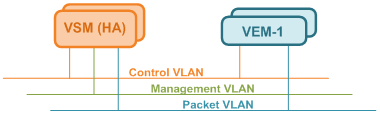
Layer 2
VSM and VEM need to be on the same Control and Packet VLAN, hence being L2-adjacent. Three required VLAN are described as follows and, by no mean, these need to have unique VLAN ID, although recommended.
Control VLAN is used by VSM to manage (or “control”) all VEM and distribute configurations, as well as by active and standby VSM to exchange heartbeats and maintain synchronization in High Availability (HA) deployment
Management VLAN is used by VSM Management interface (Mgmt0) to communicate with a vCenter to publish port configuration, coordinate VEM install on ESXi hosts, and allow remote CLI access.
Packet VLAN is used by VEM to forward any control packet (eg. CDP) received from upstream network to VSM for further processing.
Pros
- There is not really, as Layer 3 is now recommended. This is more of a legacy design since it was the only mode originally supported.
Cons
- Less flexibility as the VLAN needs to be spanned across server environment, let alone across datacenter
- Troubleshooting VSM-VEM reachability at Layer 2 is difficult
Layer 3
VSM and VEM no longer need to share VLAN, and can even be multiple Layer 3 hops apart. Compared to Layer 2 mode, the three VLANs are used as follows.
Control VLAN is exclusively used for VSM HA communication so make sure both primary and secondary VSMs are on this VLAN
Management VLAN functionality remains the same as Layer 2 mode with VSM Mgmt0 interface can potentially be used to communicate with VEM (see below)
Packet VLAN is no longer relevant and the VSM third interface can be set to any VLAN.
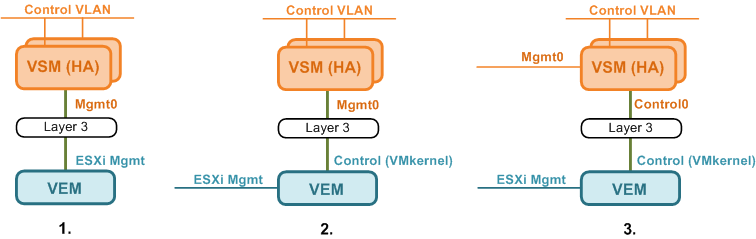
There are multiple ways to achieve communication between VSM and VEM. Regardless of the option, you need to make sure the subnets VSM and VEM L3 interfaces are on are routable.
1. VSM (Mgmt) to VEM (Mgmt) - VSM uses its default Mgmt0 interface, while VEM uses its host ESXi Mgmt interface. This is probably simplest option as no additional interface, hence IP, is required.
2. VSM (Mgmt) to VEM (Ctrl) - VSM uses its existing Mgmt0 interface, while VEM uses a dedicated VMkernel as a Control interface. This is accomplished by creating a port-profile with ‘capability l3control’ and assigning it to the VMkernel on ESXi. This option allows N1KV control traffic to be segregated from ESXi management traffic.
3. VSM (Ctrl) to VEM (Ctrl) - Both VSM and VEM use dedicated Control interfaces. On the VSM, this interface can be changed from Mgmt0 to Control0 under ‘svs-domain’ using the ‘svs mode’ command. This is probably the cleanest option with the control traffic be segregated on both VSM and VEM at the cost of additional IP; one on each VSM and one on each VEM, and potentially VLAN/subnet.
Pros
- VSM can be located almost anywhere in the network
- Packet VLAN is eliminated
- Troubleshooting VSM-VEM reachability at Layer 3 is simpler (ie. Ping)
Cons
- Additional IP and VLAN are potentially required depending on the VSM-VEM communication options described above
2. Number of Uplinks
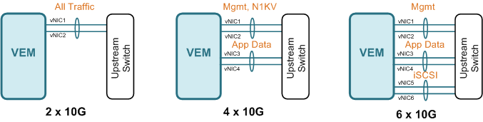
Some people prefer keeping certain traffic away from one another, for example management and application, and this requires multiple uplinks. Unless you have Cisco UCS with Virtual Interface Card (VIC) that allows almost arbitrary number of vNIC to be created, you are most likely limited by number of physical NIC the servers have, or switch module in case of server blade chassis. Regardless, you would want to keep the number of uplinks in multiple of two, preferably in port-channels, for link redundancy. Here are some of the examples
2 x 10G - With only two links, you do not have much choice but to place all traffic on a single port-channel, unless you plan to split the uplinks and do active-standby type failover. This is common in server blade chassis that only have two switch modules.
4 x 10G - With four uplinks, you can split traffic into two port-channels; ESXI management, and N1KV control on the first, and application data on the second. This is to ensure that high bandwidth utilization on the data does not affect management traffic.
6 x 10G – With six uplinks, you have three port-channels to play with. The first two could be used the same way as the four uplinks scenario, and you cloud split off N1KV control, or if you have IP storage like iSCSI or NFS, they are good candidates for the third port-channel as well.
Additional uplinks can be added under the same thought process but, keep in mind the added complexity to your design and troubleshooting. In Cisco UCS, depending on the number of connection between I/O module (FEX) and Fabric Interconnect and whether they are configured as port-channel, traffic may end up sharing the same link regardless of the number of vNIC uplink you have.
Implementation Options
1. Type of VSM
VSM comes in two form factors: VMware Virtual Machine and Virtual Services Appliance (VSA) on a dedicated Nexus 1010 or 1100 server. Usually you choose between these options based on:
- Cost
- Organization preference on keeping network devices as separate hardware
- Relationship between server and network teams
Virtual Machine
Pros
- VSM can be immediately brought up in existing VMware environment at virtually no additional cost
- VSM benefits from redundancies built into VMware
- Fast recovery in an event of hardware failure
Cons
- Access to VMware environment is required to install, manage, and troubleshoot the VSM, which might not be available, or need to be granted to network team.
- VM can be moved around across VMware environment, although knowledge of their location is usually unnecessary as long as connectivity is maintained.
Virtual Services Appliance
Pros
- The appliance can be treated as a network device and managed by network team
- Additional Virtual Service Blade (eg. VSG, NAM, DCNM) can be hosted on the same hardware
Cons
- Additional cost, power, cooling rack space etc., especially with two appliances in HA
- RMA is required upon hardware failure which may extend recovery time
2. VSM Install (VM)
Cisco provides you with multiple methods to create and initially configure a VSM virtual machine.
Manual - VM is created and hardware specification is set manually. The VM is installed from an .iso image and you will be prompted to go through setup process on the CLI.
Pros
- - You have complete control over VSM characteristic and configuration
- - L2 and L3 mode can be specified right at the beginning
Cons
- - Knowledge of minimum hardware specification of the VM is required
- - Installation and initial configuration may take longer than other methods
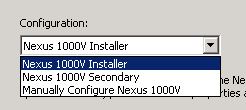
OVA – Cisco provides an OVA file as part of Nexus 1000V software package to be used as a template. Within the OVA, there are three sub-options
1. “Nexus 1000V Installer” - With this option, you are required to complete a form containing full configuration parameters, similarly to what you would encounter during the manual setup wizard. These parameters are used by the installer as inputs to run a script that automatically performs VSM initial configuration. This is usually used in creating a primary VSM (L3).
2. “Nexus 1000V Secondary” - With this options, you will be required to only enter domain ID and password of the primary VSM. This is usually used in creating secondary VSM (L3).
3. “Manually Configure Nexus 1000V” - With this option, you are NOT required to enter any parameter, although you are presented with the parameter form. Once the VM is created and booted up, you need to step through the setup process on the CLI similarly to when you create the VSM manually, where you will also be able to choose the role (Standalone/Primary/Secondary) of the VSM.
Pros
- Knowledge of VM hardware specification is not required since it is pre-defined in the OVA file
- Faster installation without being prompted for initial setup (for Option 1 and 2)
Cons
- Option 1 and 2 installs VSM in L3 mode by default, and need to be manually switch to L2 if desired
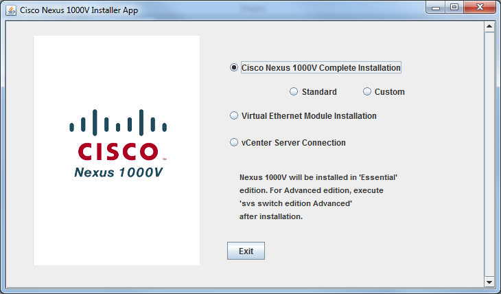
Installer App - This basically takes what OVA accomplishes one step further by combining primary and secondary VSM installation into a single procedure, and registering the VSM XML extension to a vCenter. You are required to enter all configuration parameters including ESXi host you wish to have the primary and secondary VSM installed, and even L2/L3 mode connectivity options on the installer. At the end of the installation process, you will have a functioning VSM HA pair that communicated to the vCenter. With Installer App, there are two sub-options for VSM.
1. Standard - Configurability in this mode is very limited. This includes
- L3 mode only
- VSM management interface needs to be on the same VLAN as the host ESXi management
- Same Control and Management VLAN
- Switch password and ESXi port-group name for Control and Management VLAN are automatically chosen
2. Custom - Configurability in this mode is much more extensive without any limitations exist in the Standard mode.
Pros
- Fast installation of VSM HA pair since everything is automated including VSM XML registration to vCenter
- Works well for a clean install
Cons
- Only VSM HA is supported
- Should the process fails at any given time, the whole installation needs to be started over
3. VEM Install
Similarly to VSM install, there are multiple methods to add an ESXi server to a Nexus 1000V dvSwitch.
Manual – With this option, you need to SFTP a VEM .vib file to the ESXi server and initiate an install on the CLI. This requires you to access the server via console, or SSH. Once installed, the host can be added on a vCenter.
Pros
- VMware Update Manager is not required
- Ability to choose interfaces (existing or unused) for uplinks
Cons
- Require a correct .vib file that is compatible to ESXi version
- More time consuming especially when having to work with large number of host
VMware Update Manager (VUM) - With this option, a host can be immediately added on a vCenter. VUM automatically select a correct .vib and install it.
Pros
- Simple and fast without possibility of using an incorrect .vib file
- Ability to choose interfaces (existing or unused) for uplinks
Cons
- VMware Update Manager is required
Installer APP – With this option, all you need to do is selecting an available ESXi that you wish to add to a N1KV and the rest is taken care of for you. This includes:
1. Copy active VLAN on vSwitch and configure corresponding port-profiles on VSM
2. Migrate all existing uplinks on vSwitch to N1KV
3. Add the ESXi host to N1KV using VUM
4. Migrate all (inactive) VM from vSwitch to N1KV
Note: ESXi host will not be available for selection is it has any active VM on its vSwitch.
Pros
- Manual configuration on VSM is not required
- Manual VM migration is not required
- More appropriate for green-field install
Cons
- There cannot be any active VM on the ESXi host which makes it difficult to migrate existing VM over without downtime
- Existing uplinks are converted over which makes it intrusive instead of being able to gradually migrating VM by changing VM from old to new port-group on N1KV to utilize new uplinks
- Additional configuration is still required if uplink port-channel with LACP is desired
- Not appropriate for environment with already a lot of active VM
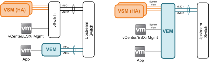
4. VSM Placement
Behind vSwitch - Some people feel more comfortable placing VSM behind a traditional vSwitch along with other critical services such as ESXi management and vCenter to make sure that reachability to these devices are not interrupted due to VSM-VEM connectivity issue. This approach is perfectly fine as long as you have sufficient number of uplinks in addition to those already assigned to the N1KV. You also need to (manually) make sure the vSwitch are configured consistently across the ESXi environment.
Behind VEM – If you decide to place VSM behind a VEM, whether by choice, or because all a server has is two uplinks and you are better off with a single port-channel uplink, you need to configure all service-critical VLAN as system VLAN. This ensures that VEM forwards traffic on those VLAN regardless of its connectivity state to the VSM. You also do not need to worry about configuration inconsistency as it is managed as part of dvSwitch.
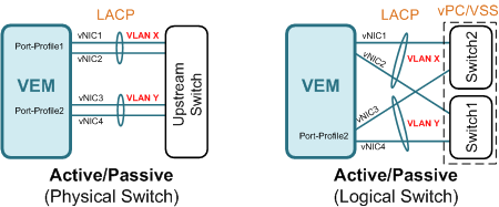
5. Type of Uplink
When you configure channel-group under uplink (type ethernet) port-profile, you are presented with basically three modes: Active/Passive, On with MAC pinning, and On with sub-group. For each mode, it is possible to create multiple channel-groups if you wish to segregate traffic on certain VLAN to use certain uplink port-channel. A general suggestion is not to have the same VLAN allowed on multiple port-channels connecting to the same physical or logical switch.
Active/Passive is recommended when you have multiple uplinks (hopefully in the power of two ie. 2,4,8 etc) connecting to a single or stackable switch capable of LACP (802.3ad), or multiple switches capable of LACP with Multi-Chassis Etherchannel (MCEC) such as VSS on Catalyst or vPC on Nexus switches.
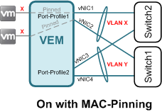
On with MAC pinning is used when you have multiple uplinks, each connecting to a different switch. With MAC pinning, traffic from a guest VM is (statically or automatically) pinned to the same uplink unless the uplink fails. No channel-group configuration is required on the upstream switch. A good example of this is Cisco UCS (B-Series) connecting to Fabric Interconnect switches.
On with sub-group is similar to 'On with MAC pinning' except that you have multiple uplinks to the same switch. Under the same port-profile, these uplinks can either be manually or automatically placed under sub-groups. For automatic sub-group, CDP is required for N1KV to discover and determine if the uplinks are connected to the same switch.
As you can see in this article, there are a lot of design and implementation considerations that need to be addressed before beginning your Nexus 1000V install. Hopefully, this article provide you with sufficient information to help you coming up with an appropriate implementation strategy for your deployment. If you have additional suggestions and inputs, please share them in the comment section below.
References:
Relevant Videos:
About Author
Metha Chiewanichakorn, CCIE#23585 (Ent. Infra, Sec, SP), is a Cisco networking enthusiast with years of experience in the industry. He is currently working as a consulting engineer for a Cisco partner. As a founder of and an instructor at labminutes.com, Metha enjoys learning and challenges himself with new technologies.
1 comments
another great read!Thank you~